Those who now can build a PC easily have all struggled in connecting the front panel cables to the motherboard. They are the most confusing thing in building a PC and no matter how many times you do it, if you take a big gap between building PCs, you might get confused in plugging in the correct cables to the correct pins.
For those who are newbies to PC building, this is the most concerning part, yet if once remembered, can be easily done every time without looking for it on the internet. But still, you can bookmark this page if you think you are gonna forget it next time building a PC.
Let’s understand the cables and headers before jumping straight into connections!
Case Ports, LED Lights, And Buttons
There are 5 different kinds of ports, 2 kinds of LED lights and 2 kinds of buttons that are usually found on most PC cases whether, ITX, M-ATX, or ATX.
The kinds of ports and buttons along with their quantity vary from case to case and your case may or may not have all of these.

The above pic is of an example of front panel ports on a case that is connected to the motherboard headers through the cables which are pre-connected to these ports.
| Port/Button | Description |
|---|---|
 | The top LED light represents Power ON/OFF while the bottom light represents Hard drive/SSD LED. |
 | The left jack is for connecting speakers or any other output audio source and the right jack is for connecting an audio input source like a microphone. |
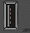 | USB 2.0 port |
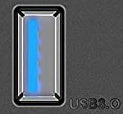 | USB 3.0 port |
 | USB Type C port |
 | Power ON/OFF button |
 | Reset button |
| Case Connectors | Description |
|---|---|
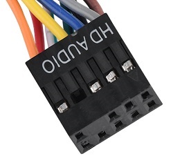 | 9-pin HD Audio connector |
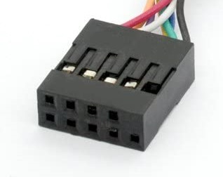 | 9-pin USB 2.0 connector |
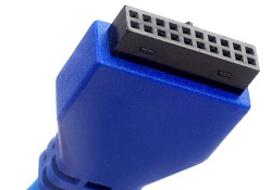 | 20-pin USB 3.0 connector |
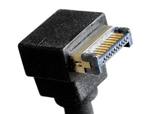 | USB Type C connector |
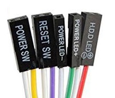 | 2-pin POWER SW connector, 2-pin RESET SW connector 1+1-pin POWER LED +/- connector, 2-pin HDD LED connector |
Motherboard To Case Connection
For connecting each and every connector that is available in your PC case, you need to have headers for their connectors on your motherboard.
Almost every motherboard comes with USB 2.0 and HD Audio headers while most motherboards do come with a USB 3.0 header but only a handful of motherboards come with a Type C header.
Power/Reset connectors and LED connectors are common across all the motherboards and are universal.
Connecting USB 2.0 connector cable
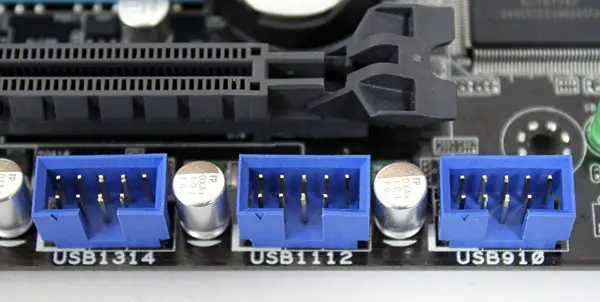
The majority of motherboards come with a single USB 2.0 header but some may come with more than one. A USB 2.0 header should contain 9 pins as shown in the image above. The 10th spot for the pin should be empty allowing you to know the correct orientation of the connector.
Connecting USB 3.0 connector cable
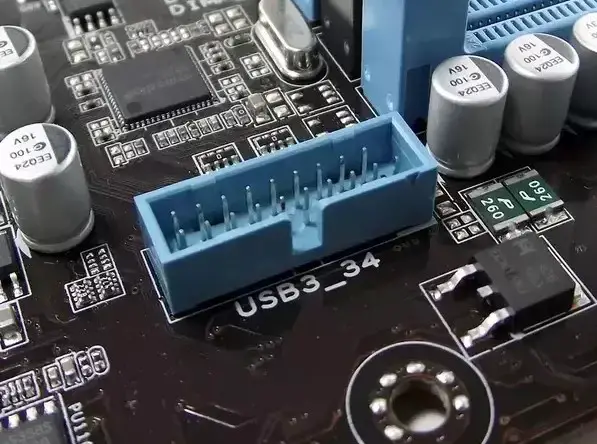
USB 3.0 header comes with 19-pins instead of 20 and has a small cut in the middle at one side to know the correct orientation for connecting the USB 3.0 connector.
Connecting HD Audio connector cable
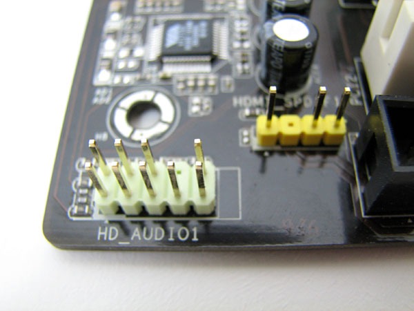
The HD Audio connector will go into the 9-pin HD Audio header on the motherboard that is generally located at the bottom of the motherboard. The Audio header is sometimes labeled as AAFP or JAUD1.
Connecting USB Type C connector cable
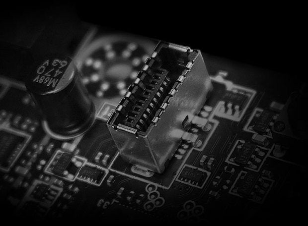
A USB Type C header looks like the above and you can’t count the pins in it easily. So, just remember how it looks. The USB Type C connector mentioned previously should go into this header which most of the time is available at the middle-right side of the motherboard near to the SATA ports or 24-pin ATX power connector.
Power, Reset, Power LED, HDD LED connection
For connecting these connectors, you need to remember the following diagram:-
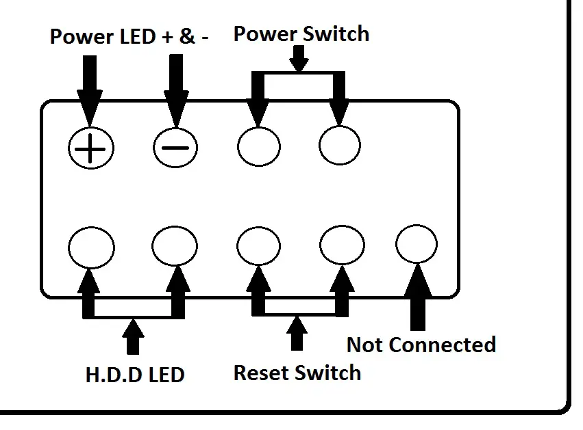
There will be 9 pins in total on the motherboard and these are generally situated at the bottom-right corner. The 9th pin is Not Connected means it has to be left without any connection.
Make sure you connect according to the Positive and Negative connotations as mentioned above.
That’s it! You have successfully learned how to connect the front panel cables from your PC case to your motherboard. Let me know if you have any queries in the comments section below.
Related:

